Basic Residential Ductwork Design
Understanding the basics of residential ductwork design is the key to ensuring your entire heating and cooling system is adequate and efficient. This page and all of its content is intended as a guideline from which to understand the basic principles of residential ductwork systems and their design. Hamilton Home Products, Inc. recommends that all residential ductwork systems be designed and installed by a qualified technician.
The purpose of residential ductwork design is to properly distribute the airflow produced by your heating/cooling system to your house. This involves return air (unconditioned) coming into the heating/cooling system. Then, by heating/cooling that air, delivering the newly conditioned air to your home. An improperly designed ductwork system can cost money through inefficiencies, and in some cases, cause premature failure of heating and cooling equipment. This means that your home’s ductwork system is just as important as the equipment used to heat and cool your home.
The 3 Most Important Things to Understand About Residential Ductwork Design:
1. Furnaces and air conditioners require a certain amount of airflow, measured in CFM (Cubic Feet Per Minute), to be passed through the equipment (supply and return ducts) in order for the equipment to function properly and efficiently.
2. All homes have unique requirements and construction that pose obstacles when designing the ductwork system to accommodate each room with proper airflow. (This is especially true with older homes.)
3. The ideal ductwork system achieves both goals by providing enough airflow to and from the heating/cooling equipment as well as the home. For maximum efficiency, this “ideal” system should also be sealed at all seams with aluminum tape, and should be properly insulated when exposed to unconditioned environments (i.e. crawl spaces and attics).
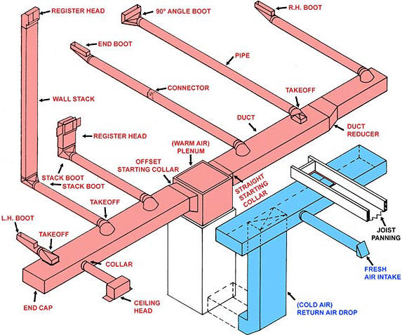
Basic Ductwork (trunk Line) Layout – Duct Work Information
This type of system incorporates the use of a “trunk line” or series of rectangular ducts that act as a main supply channel throughout the house. From these “trunk lines” come branch ducts (usually round) that extend, in various ways, to the registers which are strategically placed throughout the home.
The size of each component is determined by the airflow that needs to pass through it. The overall sizing of the “trunk line” is designed to evenly distribute the appropriate amounts of air to every register. Caution must always be used when sizing individual components to insure that the heating/cooling equipment has adequate airflow for optimum performance.
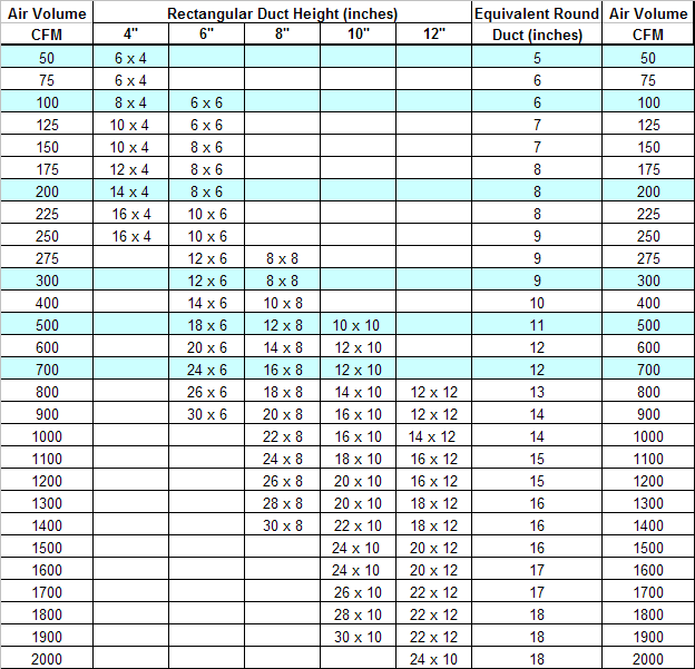
Ductwork or Duct Work Layout for airflow calculations
Rectangular Duct and Round Duct:
The duct sizes listed in the chart provided are based on a fraction drop of .10 inches per 100 feet of lineal duct. This “Equal-Friction” method of duct sizing should be adequate for normal residential furnace heating and air conditioning applications. Larger volumes or higher static pressures should be dealt with on an individual job basis.
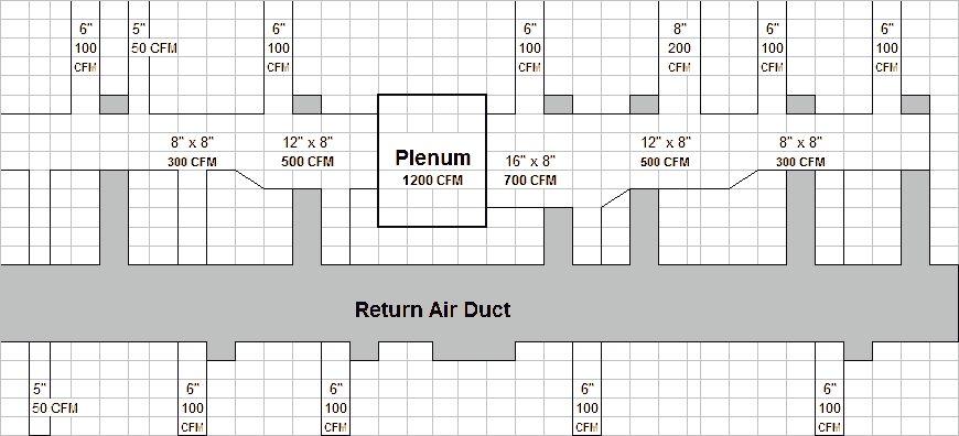
Example: Ductwork Design Layout (With CFM Ratings)
This duct system is designed to move 1200 CFM and support 3 Tons of Air Conditioning. You must have a minimum of 400 CFM of air flow per Ton of A/C to ensure the evaporator will not freeze-up.
Basic Guidelines for Ductwork Fittings and Placement:
Supplies are located on outside walls.
Returns are located on inside walls. They should not be located in the same area as the furnace, nor should they be located by moisture sources such as kitchens or bathrooms.
Return Air CFM must be equal or greater than supply Air CFM.
Wyes commonly reduce.
Tees split, but do not reduce, and an appropriate reducer must be added.
Dampers on take-off duct runs allow for adjustments of air distribution.
In order to maintain velocity, reduce duct size.
Never locate ducts at the end of the trunk line run. Last take-off run to be located 12″ – 18″ from end.
Always stagger take-off ducts by 12″ to maintain pressure.
Use insulated duct or duct board in unheated spaces.
Flexible duct work must be stretched tightly for maximum air flow.
Ductwork Related Publications:
Hamilton does not necessarily endorse or agree any information provided on these sites.
Should You Have the Air Ducts In Your Home Cleaned?
This fact sheet from the EPA helps to explain the facts and fiction about air duct cleaning. There are also tips for what to look for when having your system inspected, and when to have your air ducts cleaned.